Netgear CM500 Hacking
What? Why?
In my quest for hardware hacking, and a router that I really have control over, I decided to take apart a modem that I used to use, before I had access to Google Fiber. This thing is pretty bad - and it connects via coaxial cable - so no ethernet in for my connection. That being said, there will probably soon come a time when I no longer have access to that sweet, sweet fiber optic internet.
Realistically, this project will never make a good router, even if it succeeds. That being said, the specs are sufficient for OpenWRT, and it’s something I’d like to play with, even if it’s just to make a mini cyber-range at some point. The notes below are how I was able to get shell access. Unfortunately, I have no idea how to use that shell access, so the project is on hold for now, until I figure out how to actually get the firmware I need on the shell.
I have chosen to upload these notes in case this information is useful to anyone else! While I found that getting access to the shell was easy, and using the shell was confounding, someone out there might be in the exact opposite situation. If you happen to know what to do next, drop me a line at netgear <at> cobza.ru
Connecting.
The first successful attempt was on MacOS Monterey Version 12.4 Macbook Air (late 2015). An attempt was made to connect using windows, but it was too difficult to get any software to connect to the FTDI. I attempted using screen, but minicom was eventually what I got to work.
Minicom
The FTDI was connected to the right side USB port on the macbook air. To find out what to even connect minicom to, I used ls /dev/tty.*, and one of the devices looked suspiciously like my cheap non-genuine HiLetGo brand FTDI. I pasted that after sudo minicom --device and ended up with:
sudo minicom --device /dev/tty.usbserial-A5XK3RJT.
Minicom did not come with this mac, so I had to install it using brew. My terminal is currently running OhMyZsh. All particulars are included purely for reproducibility.
Console Access
For the first <5 seconds after boot, the shell will accept UART input. After the default boot image loads (of which there are two, but we’ll get back to that in a bit), you are asked which boot image to load. It will show three choices, which are 1, 2, or p, though there is no point in pressing anything other than p, by default. The second image is probably to allow self updating the entire image by transferring into a second slot. The p image might stand for programming, as it loads you into a menu giving you very low level access.
Next Steps:
- Look up examples of hardware hacking on other routers/modems
- Look up datasheet for memory chip (if possible), learn about memory address space
- Create a python script that uploads new firmware, one mem page at a time???
- Dump the OS image
- Make changes to the image, and compile a new one
- Upload new firmware, and enjoy a more unlocked modem
Technical Data.
Board UART Pins.
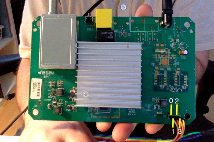
The pin on the far left (furthest from the bottom right mounting hole on board, with the brown cable attached) will be referred to as PIN0, and the pin on the far right (with the yellow cable attached) will be referred to as PIN3.
| Pin | Value | Color |
|---|---|---|
| PIN0 | RX ? | Brown |
| PIN1 | TX | Red |
| PIN2 | GND | Orange |
| PIN3 | VCC ? | Yellow |
Where color refers to color in image above, purely for ease of understanding.
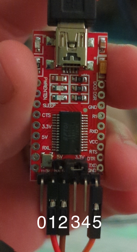
FTDI Connections.
| Modem | Value | FTDI | Value |
|---|---|---|---|
| PIN0 | RX ? | PIN1 | RX |
| PIN1 | TX | PIN2 | TX |
| PIN2 | GND | PIN5 | GND |